Fringing Field In Microstrip Patch Antenna Primer
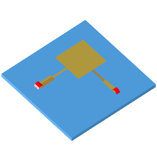
Micro-strip Patch Antenna Primer J P Silver. Fringing fields between the edges of the. Figure 3 Rectangular microstrip patch antenna electric field patterns.
Diagram of the feed structure of a microstrip antenna array. Mc Hammer Discography Rare. In, a microstrip antenna (also known as a printed antenna) usually means an fabricated using techniques on a (PCB). They are mostly used. An individual microstrip antenna consists of a patch of metal foil of various shapes (a ) on the surface of a PCB, with a metal foil on the other side of the board.
Most microstrip antennas consist of multiple patches in a two-dimensional array. The antenna is usually connected to the or through foil.


The current is applied (or in receiving antennas the received signal is produced) between the antenna and ground plane. Microstrip antennas have become very popular in recent decades due to their thin planar profile which can be incorporated into the surfaces of consumer products, aircraft and missiles; their ease of fabrication using techniques; the ease of integrating the antenna on the same board with the rest of the circuit, and the possibility of adding active devices such as to the antenna itself to make. Main article: The most common type of microstrip antenna is the. Antennas using patches as constitutive elements in an array are also possible.
A patch antenna is a narrowband, wide- antenna fabricated by etching the antenna element pattern in metal trace bonded to an insulating substrate, such as a, with a continuous metal layer bonded to the opposite side of the substrate which forms a. Common microstrip antenna shapes are square, rectangular, circular and elliptical, but any continuous shape is possible. Some patch antennas do not use a dielectric substrate and instead are made of a metal patch mounted above a ground plane using dielectric spacers; the resulting structure is less rugged but has a wider. Because such antennas have a very low profile, are mechanically rugged and can be shaped to conform to the curving skin of a vehicle, they are often mounted on the exterior of aircraft and spacecraft, or are incorporated into communications devices. Advantages [ ] Microstrip antennas are relatively inexpensive to manufacture and design because of the simple 2-dimensional physical geometry. They are usually employed at and higher frequencies because the size of the antenna is directly tied to the at the. A single patch antenna provides a maximum directive gain of around 6-9.
It is relatively easy to print an array of patches on a single (large) substrate using lithographic techniques. Patch arrays can provide much higher gains than a single patch at little additional cost; matching and phase adjustment can be performed with printed microstrip feed structures, again in the same operations that form the radiating patches. The ability to create high gain arrays in a low-profile antenna is one reason that patch arrays are common on airplanes and in other military applications. Such an array of patch antennas is an easy way to make a of antennas with dynamic ability. An advantage inherent to patch antennas is the ability to have diversity.