Software Serial Esp8266 Pinout
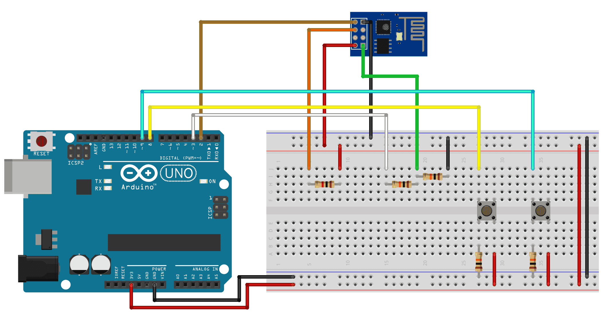
Espsoftwareserial - Implementation of the Arduino software serial for ESP8266. How to Use the ESP8266-01 Pins. On power-up to indicate to the software that you. In either case TX / RX are also available for Serial debugging or if you. In this tutorial we will show how to connect ESP8266 WiFi module to Arduino. We will use software serial port. HW serrial port will be available for program uploading.
I have been playing with an ESP8266 over the last couple of days with similar results. My conclusion was that it is very timing dependent.
If you build in (fairly large) delays into your code then you will find it works better. The delays are effectively what you are doing as you type in each new command.

I found, for example, that the AT+CWJAP (join access point) command takes quite a while, like 10 seconds or so. Preferably don't use 'actual' delays because they are blocking (unless you don't care about that). You could have a list of commands you want to send, and a system that pulls the next one out of the list when a certain time has elapsed. If you use something like 5 to 10 second delays between commands you should get better results. At the very least, after sending one command, look for a confirmation string from the device (eg.

OK, ERROR etc.).
Tue Jun 23, 2015 8:22 pm Is this similar to SoftwareSerial as used in Arduino? This from Github ESP8266/Arduino - Read me Serial Serial object works much the same way as on a regular Arduino.
Apart from hardware FIFO (128 bytes for TX and RX) HardwareSerial has additional 256-byte TX and RX buffers. Both transmit and receive is interrupt-driven. Write and read functions only block the sketch execution when the respective FIFO/buffers are full/empty.
Serial uses UART0, which is mapped to pins GPIO1 (TX) and GPIO3 (RX). Serial may be remapped to GPIO15 (TX) and GPIO13 (RX) by calling Serial.swap(); after Serial.begin(). Calling swap again maps UART0 back to GPIO1 and GPIO3. Serial1 uses UART1 which is a transmit-only UART. UART1 TX pin is GPIO2.
To use Serial1, call Serial1.begin. By default the diagnostic output from WiFi libraries is disabled when you call Serial.begin. To enable debug output again, call Serial.setDebugOutput(true).
To redirect debug output to Serial1 instead, call Serial1.setDebugOutput(true). Both Serial and Serial1 objects support 5, 6, 7, 8 data bits, odd (O), even (E), and no (N) parity, and 1 or 2 stop bits.
To set the desired mode, call Serial.begin(baudrate, SERIAL_8N1);, Serial. Crack Para The Suffering 2 Pc more. begin(baudrate, SERIAL_6E2);, etc. However if you feel this would be useful then I suggest you go to the ESP8266/Arduino site and write a new issue and see what Igrr thinks.I am sure he could get it in easily enough.